
Robotic arm project with Arduino
DYI - Robotic arm with Servo motors
Automation is one of the leading development fields mainly because it advances the industry further than ever before, providing the potential of almost fully automated production lines. Automation is stated to be the 3rd phase of the industrial revolution. A remarkable technological advancement that pushes mankind up a step in the ladder of industry tech. It makes products cheaper to produce and at larger quantities making the technology worthwhile to invest in. Since the beginning of the industrial revolution mechanical engineers developed machines to ease on the workforce. Electricity and computer science provided the gateway to something new – robotics! Automized machines capable of human activity. So current technology allows us to build machines that are capable of performing human-like actions. To do so, robots must have similar autonomy consisting moving parts that are electromechanically driven and a “brain” component to control them by following pre-determined instructions, or make them make up on its own!
How to make a robotic arm
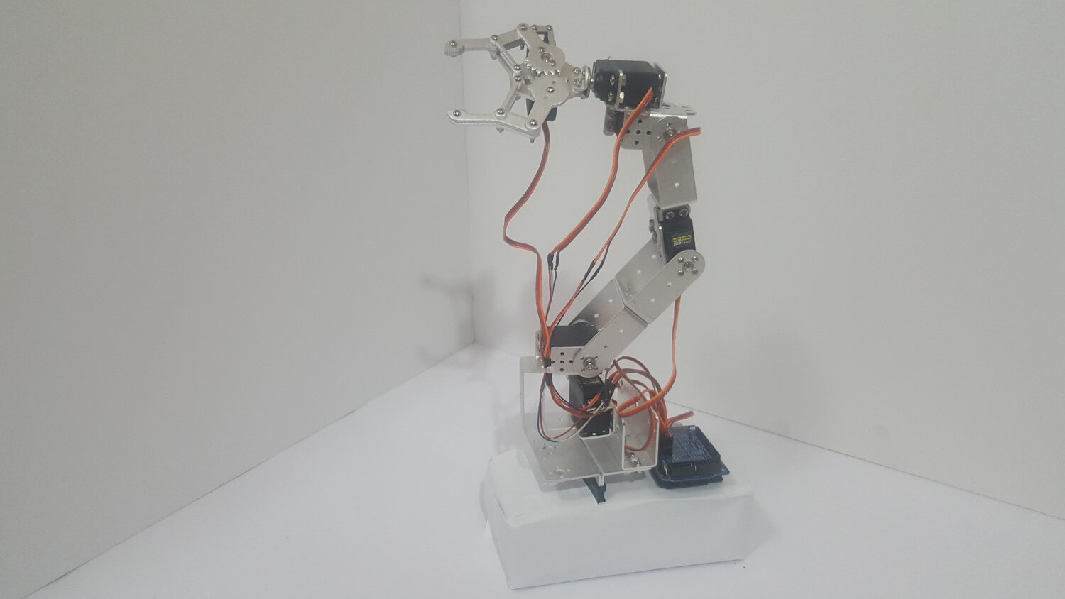
In this project we will build the basis for an automated programmable robotic arm. We shall learn how to construct and control a 6 axis robot arm via a control interface from a computer, and write pre-determined instructions for it to follow and repeat. We will use servo motors to drive the parts and an Arduino UNO as our microcontroller that will control them while communicating with the PC via a USB cable.
For this project please download our control software.
Programming languages used in this project:
C (Arduino IDE)
Hardware
Mechanics:
Some 6DOV DIY robot arm kits come with all relevant parts included, while others don’t. In my case, I ordered the kit and then realized it did not include the motors and the disks. So I had to order them separately. However, the advantage of ordering the parts separately is the flexibility of choosing the motors that will be used in the project. So I chose the DMS15-270 motor which has a wide 270 degree range rather than the more common MG996R that reaches only about 120 degrees. This extended the flexibility and range of my robotic arm.
Assembling the arm should be done carefully and can take an hour or two. Fasten the bolts tightly to minimize dangling parts – but not too tight.
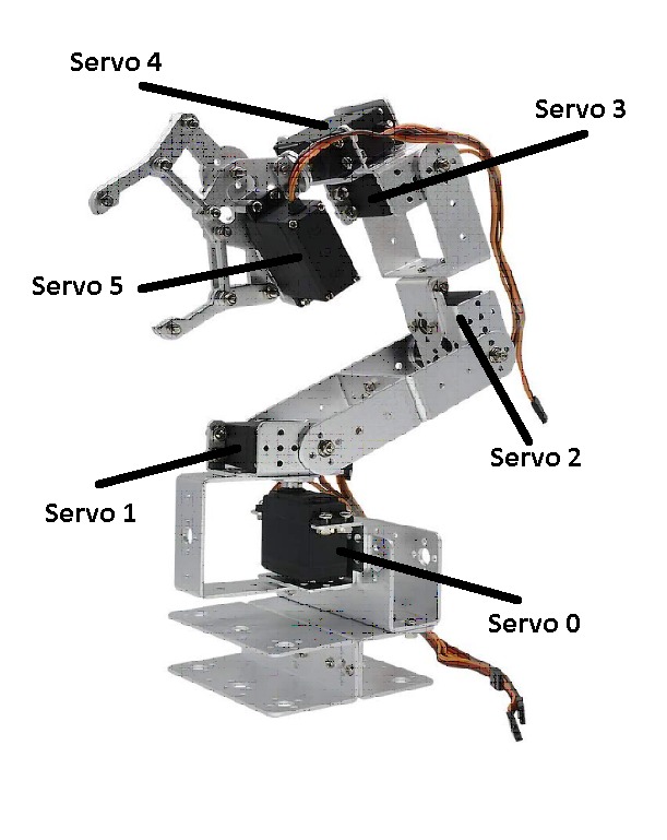
While assembling the motors, pay attention to the side that motors 1, 2 and 3 are facing. This will affect the direction the arm will move, since the spin of the motors is controlled by a Windows application. Also, if the 3-wire cable is not long enough to reach the ground when the arm is fully stretched, you will have to cut the cable and extend it with additional wires.
When assembled, install the arm on a fixed foundation. Because when it moves it has a strong impulse, the arm must be fixed to a stable platform to avoid falling over. I personally taped the base of the arm to a brick and it worked fine.
Electrics
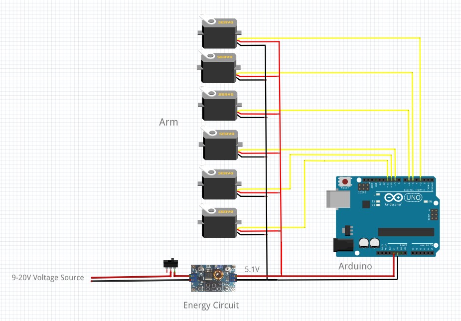
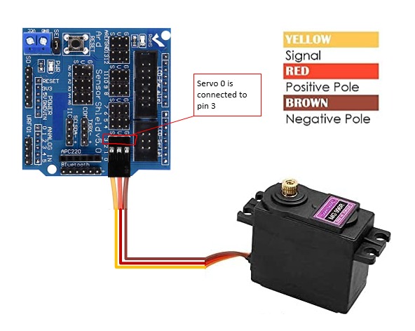
The circuit is fairly simple. No need for an engineering degree. Connect all of the servo motors to power in parallel. Brown wire is (-) and red wire is (+). The control wires which are colored orange or yellow go to the PWM pins of the Arduino. These are pins 3, 5, 6, 9, 10 and 11. I recommend using a shield compatible with all the I/O pins that provides parallel power lines to which you can solder regular pins. This way it is easier to connect the servos using their 3-pin female connectors.
Powering up the system from a USB cable is not enough. We’ll need an external power source. I’m using a 12V lithium battery connected to a DC-DC step down BUCK converter. We’ll need a module that is capable of supplying 4A peak current. The XL4015 based circuits are very efficient as they lower the voltage and raise the current to the load at a 90% efficient rate. Set the output voltage to 5.1V. Measure the voltage with a DMM if the board doesn’t have an on-built display.
Do not use voltage regulators for this sake or in any project that requires voltage regulation at high currents, because basic zener voltage regulators like the LM7805 don’t generate current gain and therefore are very inefficient and will heat up quickly.
Refer to the schematic. Do not power up motors before uploading the software, because you still need to calibrate them to their default positions.
We want to build a programmable and controllable arm. For that we need an interface that shows all the controls. Programming the robot arm to run pre-built commands will also be available through the interface. The best way to maintain this requirement is via computer software. For this purpose we developed a .NET framework windows application which is available for download for free. It will communicate with the Arduino board via USB interface, whereas the Arduino will serve as a bridge between the PC and the motors.
Software
Calibration
Please watch the following video to know how to control and use the interface and calibrate the arm. Before watching the video and following the steps, Disengage the parts of the arm that are connected to the motors.
If you still didn’t download the zip file containing the control software you can download here:
Control softwareRelease the 4 screws that are holding the servo disks of all motors. After uploading the code to the Arduino UNO board you can connect the motors and it will rotate them to their default positions. Run “Robot arm control” program, select the Serial PORT COM. See the video on how to calibrate the arm and then you can fasten all of the screws again after positioning the entire limb according to the video. After that, carefully try to move each motor a few degrees just to see if it’s moving the related part to the predicted direction. Make sure that the limits of the motors reach their physical boarders.
The default positions of the arm at power-on are:
- servo 0: 90
- servo 1: 120
- servo 2: 90
- servo 3: 120
- servo 4: 120
- servo 5: 0
The Arduino is used only to get USB frames sent from the PC an navigate the motors of that drive the arm accordingly. It will obey the following algorithm:
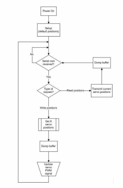
Upload the following code to your Arduino:
| 1. | "text-[#c62828]">//Arduino Robotic Arm Control Spftware |
| 2. | "text-[#c62828]">//Robotocs & Energy |
| 3. | "text-[#c62828]">//March, 2020 |
| 4. | #include <Servo.h> |
| 5. | #include <string.h> |
| 6. | Servo servo_0,servo_1,servo_2,servo_3,servo_4,servo_5; "text-[#c62828]">// create servo objects to control a servo |
| 7. | String received = ""; |
| 8. | String servo[6] = {"000", "000", "000", "000", "000", "000"}; |
| 9. | int pos[6] = { 90, 120, 90, 120, 120, 0 }; |
| 10. | int dump; |
| 11. | char c; |
| 12. | void dataHandle(String line) |
| 13. | { |
| 14. | int servoNum; |
| 15. | int lineIndex = 0; |
| 16. | int valueIndex = 0; |
| 17. | for(servoNum = 0; servoNum < 6; servoNum++) |
| 18. | { |
| 19. | while(line[lineIndex] != ' ' && line[lineIndex] != 'e') |
| 20. | { |
| 21. | servo[servoNum][valueIndex] = line[lineIndex]; |
| 22. | valueIndex++; |
| 23. | lineIndex++; |
| 24. | } |
| 25. | lineIndex++; |
| 26. | pos[servoNum] = (servo[servoNum].toInt() / pow(10, 3 - valueIndex)); |
| 27. | valueIndex = 0; |
| 28. | } |
| 29. | } |
| 30. | void armPosUpdate() |
| 31. | { |
| 32. | servo_0.write(((float)180/270)*pos[0]); |
| 33. | servo_1.write(((float)180/270)*pos[1]); |
| 34. | servo_2.write(((float)180/270)*pos[2]); |
| 35. | servo_3.write(((float)180/270)*pos[3]); |
| 36. | servo_4.write(((float)180/270)*pos[4]); |
| 37. | servo_5.write(((float)180/270)*pos[5]); |
| 38. | } |
| 39. | String readServoPositions() |
| 40. | { |
| 41. | int i; |
| 42. | String poses = ""; |
| 43. | pos[0] = ((float)servo_0.read()*1.5); "text-[#c62828]">//270/180 = 1.5 |
| 44. | pos[1] = ((float)servo_1.read()*1.5); |
| 45. | pos[2] = ((float)servo_2.read()*1.5); |
| 46. | pos[3] = ((float)servo_3.read()*1.5); |
| 47. | pos[4] = ((float)servo_4.read()*1.5); |
| 48. | pos[5] = ((float)servo_5.read()*1.5); |
| 49. | for(i = 0; i<6; i++) |
| 50. | { |
| 51. | poses += String(String(pos[i]) + " "); |
| 52. | } |
| 53. | return poses; |
| 54. | } |
| 55. | void servoStatus() |
| 56. | { |
| 57. | int i; |
| 58. | for (i = 0; i < 6; i++) |
| 59. | { |
| 60. | Serial.println(String("Servo " + String(i) + ": " + String(pos[i]) + '\n')); |
| 61. | delay(10); |
| 62. | } |
| 63. | } |
| 64. | void setup() |
| 65. | { |
| 66. | pinMode(13, OUTPUT); |
| 67. | digitalWrite(13, LOW); |
| 68. | servo_0.attach(3); |
| 69. | servo_1.attach(5); |
| 70. | servo_2.attach(6); |
| 71. | servo_3.attach(9); |
| 72. | servo_4.attach(10); |
| 73. | servo_5.attach(11); |
| 74. | armPosUpdate(); |
| 75. | Serial.begin(115200); |
| 76. | Serial.write("start"); |
| 77. | } |
| 78. | void loop() |
| 79. | { |
| 80. | if(Serial.available()>0) |
| 81. | { |
| 82. | delay(20); |
| 83. | do |
| 84. | { |
| 85. | c = Serial.read(); |
| 86. | if (c == 'u') |
| 87. | { |
| 88. | Serial.println(String("Update: " + readServoPositions())); |
| 89. | delay(10); |
| 90. | break; |
| 91. | } |
| 92. | else received += c; |
| 93. | } |
| 94. | while (c != 'e'); |
| 95. | while(Serial.available()>0) dump = Serial.read(); "text-[#c62828]">// dump buffer |
| 96. | if(c != 'u' && received != "") |
| 97. | { |
| 98. | Serial.println(String("Received: " + received)); |
| 99. | dataHandle(received); |
| 100. | armPosUpdate(); |
| 101. | received = ""; |
| 102. | } |
| 103. | } |
| 104. | } |
Summary
Building a robotic arm can be quite a challenge, because it requires proficiency in numerous engineering fields. Nevertheless, you are now able to build your own robot arm. Feel free to build a robotic arm of your own to further develop the both challenging and exciting field of robotics!
Thank you
We thank you for learning and hopefully completing our project. We are looking forward to hear from you in the comment section. Questions and constractive critisizm is welcome.